Given the scale of a technical drawing, convert any distance to its actual length.

Being able to accurately measure using a scale ruler is an important skill when working with scaled drawings. Scale drawings are used to communicate the dimensions of a full-size project on a paper or electronic document. The selected scale is usually in the title block in the lower-right corner of the drawing, but may be located anywhere on the plans. A set of drawings may include more than one scale, so you must check each drawing page for its scale. Some drawings may even have multiple scales on the same sheet. Occasionally, several details may need to be called out, but they may not be large enough to require their own sheet. Check the identifying information adjacent to the item to confirm its scale. Converting the scale length to actual length is required to determine actual height, length, width and cable run estimates.

Two different scale systems can be found on drawings: U.S. customary and metric.

Drawings using U.S. customary measurements usually state a scale using a particular fraction of an inch to represent a foot. For example, you might find a scale on a drawing that shows 1/4 inch equaling 1 foot, as shown in the picture below.

This means that a 1/4 inch length on the drawing is equal to a 1 foot length in reality. The 1/4 inch = 1 foot scale is the most common in the U.S. and is also referred to as 1/48 size because there are 48 units of 1/4 inch in 12 inches.

Shown below are two different U.S. customary scales. The 1/4 inch scale on the left indicates that for every 0.25 inches measured there is 1 foot of real distance.

Most regions outside of the United States use the metric (SI) System of units. Millimeters are the standard unit used in architectural drawings and construction language for commercial projects. 1:50 and 1:100 are the most common scales. This means that, for a drawing using 1:100, 1 unit of length on a drawing equals 100 units of the same length in reality.

1:20, 1:10, and other larger scales are generally only used for details. 1:200, 1:500, and 1:1000 are only used for very small scale drawings with little detail, such as the whole floor of a large building or a site plan.

A metric scale ruler is shown below. The 1:50 scale on the left indicates that for every 1 millimeter measured, there are 50 millimeters of real distance. The adjacent markings show that the ruler is reading 1950 mm for the room dimension, which is the same as the dimension printed on the drawing. Note that below these marking is the 1:500 scale.

Message Box 6 Icon
Quick Tip: Metric Scaled Drawings

If the scale of a metric drawing is 1:50, every unit that you measure on the drawing translates into 50 units in the actual room. You could measure with a normal ruler (metric or inches) and multiply the measurement by the scale.

If you measured 51 millimeters on a 1:50 drawing using a normal metric ruler, the length of the actual object would be 51 x 50 = 2,550 millimeters. If you then measured the same item using an normal inch ruler, you would get a reading of just over 2 inches, which converts to 2 x 50 = 100 inches. Allowing for reading accuracy, the two measurements are almost identical - 2,500 millimeters = 100.39 inches.

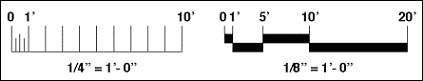
Always note the scale on the drawing. Also, check that the printed physical scale of the drawing is correct.

Consider what would happen if you took a drawing that is the correct scale on a piece of U.S. Letter sized paper that is 8.5 inches x 11 inches (216 mm x 279 mm) and tried to print it on metric A4 paper that is 210 mm x 297 mm (8.27 inches x 11.7 inches). The printer may rescale the image to fit the different sized paper, which will result in an inaccurate print-out.

All of your measurements taken from these printed copies would be incorrect. So, not only should you verify the scale of the drawing, but you should verify its accuracy.

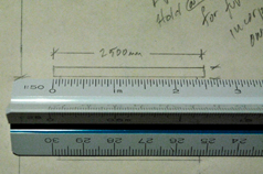
You should always check that the document was printed out accurately before making measurements and conversions. Make sure all construction drawings are printed out so that 1 unit of the printed document equals 1 unit of the original drawing. This can be done by checking the measurement of a dimensioned object or an object of known size.

Drawings can be inaccurate due to any form of copying or processing. While most original plots from a CAD file should be accurate (though human mistakes can and do happen), anything which has been plotted to "fit" the sheet of paper, rather than to a specific scale, is likely to be mis-scaled. All copies of drawings created or modified by printing (as distinct from plotting), photocopying, faxing, or turning into a PDF almost certainly are not accurate.